Page 81 - 机械工程材料2024年第十一期
P. 81

邸英南,等:不同冶炼工艺生产H13钢中非金属夹杂物特征及其对力学性能的影响


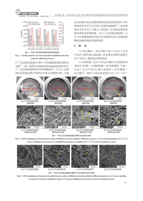
                    2 200   抗拉强度          屈服强度      80          在这些细小的夹杂物和基体处形成显微孔洞,并在
                            断面收缩率         断后伸长率     70                                              [16]
                    2 000                                       滑移的作用下长大并相互连接形成韧窝                      ,这些韧
                                                    60
                    1 800                           50          窝分布均匀且尺寸较小,因此该工艺冶炼试验钢表
                    强度/MPa  1 600                   40   30 断面收缩率、断后伸长率/%  现出更好的拉伸性能。在3 工艺冶炼试验钢中,大
                                                                                         #
                                                                尺寸且坚硬的镁铝尖晶石夹杂物的存在以及碳化物
                    1 400
                                                    20          颗粒的破碎致使其塑性较低。
                    1 200
                                                    10
                    1 000                           0           3 结 论
                         1 工艺冶 2 工艺冶 3 工艺冶 4 工艺冶
                          #
                                       #
                                              #
                                 #
                         炼试验钢 炼试验钢 炼试验钢 炼试验钢
                                                                    (1)真空感应+真空自耗(VIM+VAR)工艺生
                      图 4 不同工艺冶炼试验钢的室温拉伸性能
              Fig. 4 Tensile properties at room temperature of different test steels   产的H13钢中硫含量较低,非金属夹杂物含量较少
                           smelted by different processes       且尺寸较小,钢材的洁净度较高。
               #
              4 工艺冶炼试验钢(位置4)中发现硫化锰类型的夹                              (2)4种冶炼工艺生产的H13钢回火后的组织均
              杂物  [6-7] 。第二相质点对韧窝的形核起到重要的作用。                    为回火马氏体+未溶碳化物+析出碳化物。VIM+
              1 工艺冶炼试验钢中的夹杂物数量少、尺寸小,这使                          VAR工艺生产的H13 钢与电弧炉+炉外精炼+
               #
              得其在拉伸过程中需要经历更大的塑性变形,才能                            真空脱气+保护气氛电渣重熔 (EAF+LF+VD+


                                              图 5 不同工艺冶炼试验钢拉伸断口的 SEM 形貌
                                                                                                        #
                                                                                                          #
                                                                                                            #
              Fig. 5 SEM morphology of tensile fracture surface of different test steels smelted by different processes: (a–d) overall morphology of 1 , 2 , 3 , 4   #
                                                                              #
                                                                                #
                                                                                  #
                        process smelting test steels and (e–h) magnified morphology of radialarea of 1 , 2 , 3 , 4  process smelting test steels
                                                                            #


                                           图 6 不同工艺冶炼试验钢拉伸断口中夹杂物的 SEM 形貌
               Fig. 6 SEM morphology of inclusions on tensile fracture surface of different test steels smelted by different processes: (a) 1  process smelting
                                                                                                 #
                                   #
                          test steel; (b) 2  process smelting test steel; (c) 3  process smelting test steel and (d) 4  process smelting test steel
                                                                                 #
                                                         #
                                                                                                           73
   76   77   78   79   80   81   82   83   84   85   86